Design, Optimization, and Testing of a 3D Printed Bridge
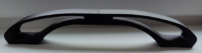
Final 3D printed bridge model capable of withstanding 100-500N loads
Problem Statement
To design, fabricate, and test a 3D-printed bridge capable of withstanding a minimum load of 100 N and failing at or before 500 N. The bridge had to adhere to strict geometric and manufacturing constraints while being optimized for minimal weight and maximum structural efficiency.
Team Members
My Role
Testing & Analysis Lead
- Designed the experimental procedure and testing setup
- Executed mechanical load tests and collected performance data
- Analyzed simulation data from ANSYS and interpreted failure modes
Design Optimization
- Optimized CAD models for structural integrity and printability
- Provided feedback for iterative redesign and print parameter tuning
Tools & Skills Used
Software
- Siemens NX - CAD Modeling
- ANSYS Workbench - Static Structural Analysis
- Altair Inspire - Topology Optimization
- Ultimaker Cura - 3D Print Slicing
Hardware & Testing
- Artillery Sidewinder X1 - 3D Printer
- Custom Test Rig - For Load Testing
- Digital Scales - For Weight & Force Measurement
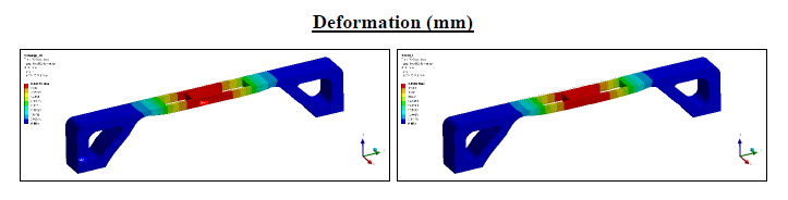
ANSYS simulation environment showing deformation analysis of the bridge model
Design & Engineering Process
1. Conceptualization & Selection
We began by evaluating different bridge types using a Pugh Matrix to systematically compare arch, truss, and beam designs based on four key criteria:
- Structural strength
- 3D printability
- Material cost efficiency
- Aesthetic appeal
The analysis led us to select an arch bridge design as the optimal solution for our constraints.
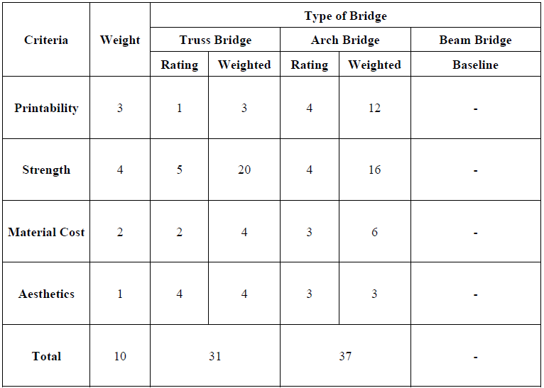
Pugh Matrix analysis of different bridge concepts
2. CAD Development
Using Siemens NX, we developed multiple iterations of the bridge, focusing on:
- Initial design with push-fit joints for modular assembly
- Later iterations incorporating Japanese carpentry-inspired interlocking joints for enhanced structural integrity
- Parametric optimization of arch curve, support structures, and cross-sectional profiles
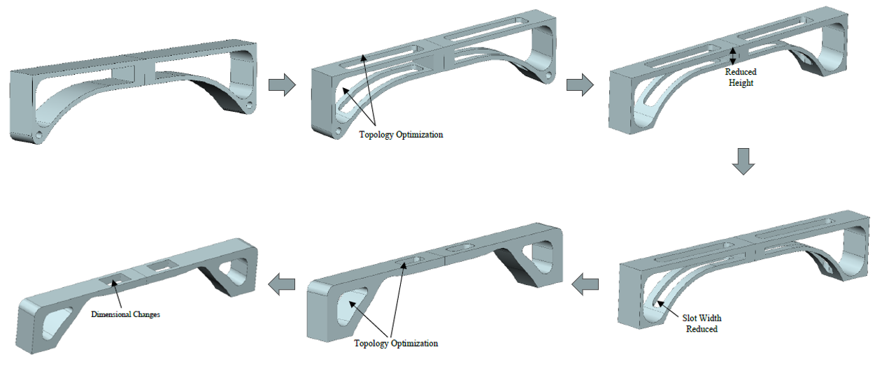
CAD model evolution showing iterative design improvements
3. FEA Simulation
We conducted comprehensive simulations in ANSYS Workbench to analyze:
- Stress distribution under varying load conditions
- Deformation patterns and potential weak points
- Factor of safety across the entire structure
The old model didnt meet the required performance standard and the design was scrapped. We came up with a new arch design with carpenter joint.
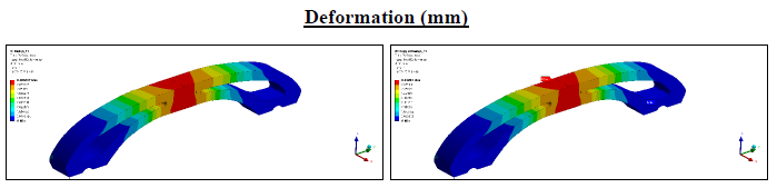
FEA results showing deformation under load
4. 3D Printing Optimization
The printing process required careful tuning of parameters to balance strength, weight, and print time:
- Tested various infill patterns (gyroid, cubic, triangular) and densities (15-30%)
- Optimized support structures to minimize material usage while ensuring printability
- Determined optimal print orientation to align layer lines with load paths
- Fine-tuned print speed and temperature settings for maximum layer adhesion
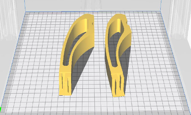
Bridge components during the printing process on the build plate
5. Iterative Testing
We built custom test rigs to evaluate the bridge's performance:
- Initial tests at 100 N (design load) to verify minimum performance requirements
- Progressive loading tests to identify onset of deformation
- Failure testing to determine maximum load capacity and fracture patterns
- Design refinements based on observed failure modes
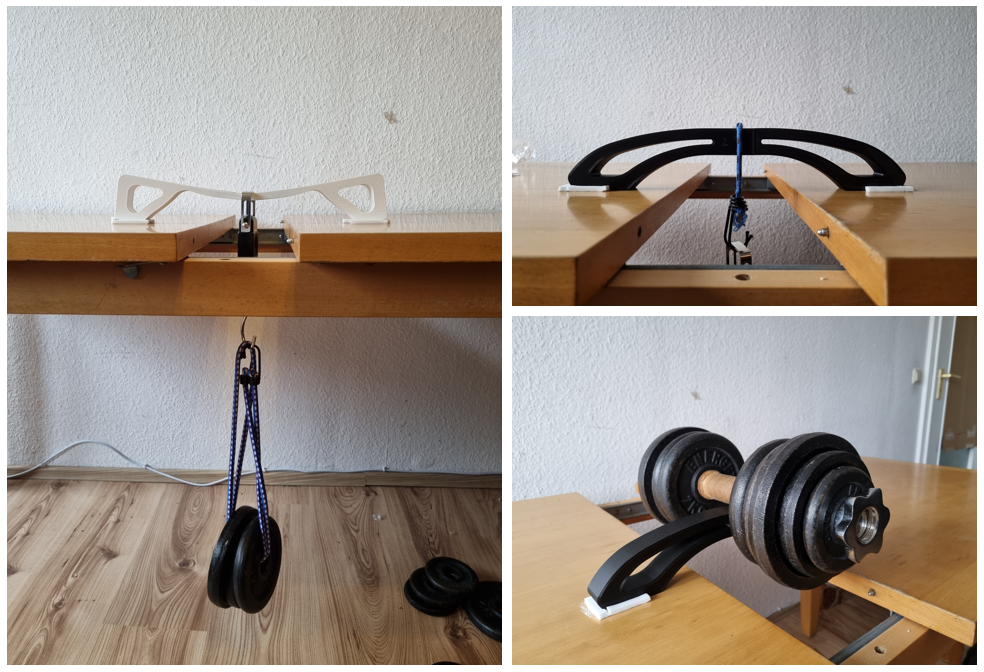
Custom test rig setup for load testing the printed bridge
Results & Outcome
Final Design
Our final bridge design achieved optimal performance metrics:
- Weight: 147 grams
- Print Time: ~16 hours
- Material: PLA with optimized infill patterns
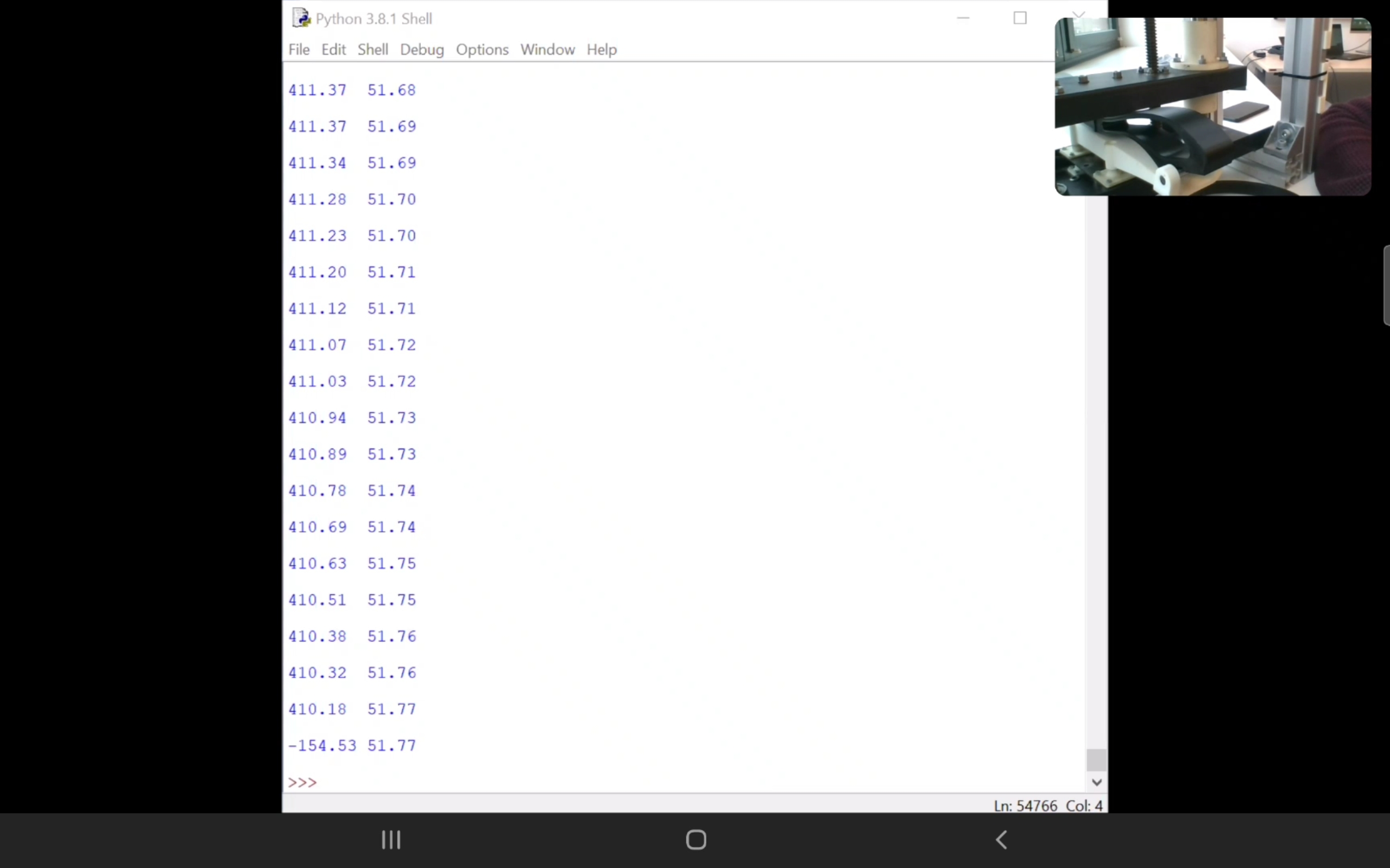
Load Testing
The bridge performed precisely within project requirements:
- Successfully withstood the design load of 100 N with minimal deformation
- Fractured just under the 500 N threshold, meeting the upper load constraint
- Exhibited predictable and consistent failure mode aligned with simulation predictions
Learning Outcomes
This project provided valuable hands-on experience in:
- CAD-CAE integration for structural design
- Additive manufacturing workflows and optimization
- Material behavior under load conditions
- Engineering testing methodology and data analysis
Completed bridge undergoing final load testing